Linux内核初始化时,最初工作在CPU实地址模式下,然后进入保护模式。那么内核代码在哪里进入初始化CPU,让进入64位(x86_64)模式?
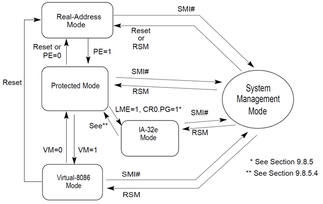
Intel 64 CPU中,支持IA-32和IA-32e两种模式,如下图。IA-32e模式就是支持64位程序运行,也支持传统的32位程序运行。在Linux内核初始化时,要进入64位模式,就是进入Intel CPU的IA-32e模式。
本文以内核源码2.6.32-71.el6为例,切换到64位CPU模式源码在arch/x86/boot/compressed/head_64.S中。对于下面的设置步骤理解,可参考《Intel 64 and IA-32 Architectures Software Developer’s ManualVolume 3 (3A & 3B) System Programming Guide March 2011》.
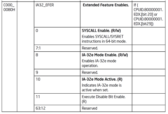
这里补充一下IA32_EFER寄存器的含义。IA32_EFER寄存器是Intel CPU中的其中一个MSR(Model-Specific Registers)。在读写这个MSR寄存器之前,必须要先通过CPUID指令来确认这个寄存器是否存在。
|
00100: / * 00101: * Prepare for entering 64 bit mode 00102: */ 00103: 00104: / * Load new GDT with the 64bit segments using 32bit descriptor */ 00105: leal gdt(%ebp ), %eax 00106: movl%eax, gdt+2(%ebp ) 00107: lgdt gdt(%ebp ) 00108: 00109: / * Enable PAE mode */ 00110: xorl %eax, %eax 00111: orl $(X86_CR4_PAE), %eax 00112: movl%eax, %cr4 00113: 00114: / * 00115: * Build early 4G boot pagetable 00116: */ 00117: / * Initialize Page tables to 0 */ 00118: leal pgtable(%ebx), %edi 00119: xorl %eax, %eax 00120: movl$((4096*6)/ 4), %ecx 00121: rep stosl 00122: 00123: / * Build Level 4 */ 00124: leal pgtable + 0(%ebx), %edi 00125: leal 0x1007 (%edi), %eax 00126: movl%eax, 0(%edi) 00127: 00128: / * Build Level 3 */ 00129: leal pgtable + 0x1000(%ebx), %edi 00130: leal 0x1007(%edi), %eax 00131: movl$4, %ecx 00132: 1: movl%eax, 0x00(%edi) 00133: addl $0x00001000, %eax 00134: addl $8, %edi 00135: decl %ecx 00136: jnz 1b 00137: 00138: / * Build Level 2 */ 00139: leal pgtable + 0x2000(%ebx), %edi 00140: movl$0x00000183, %eax 00141: movl$2048, %ecx 00142: 1: movl%eax, 0(%edi) 00143: addl $0x00200000, %eax 00144: addl $8, %edi 00145: decl %ecx 00146: jnz 1b 00147: 00148: / * Enable the boot page tables */ 00149: leal pgtable(%ebx), %eax 00150: movl%eax, %cr3 00151: 00152: / * Enable Long mode in EFER (Extended Feature Enable Register) */ 00153: movl$MSR_EFER, %ecx 00154: rdmsr 00155: btsl $_EFER_LME, %eax 00156: wrmsr 00157: 00158: / * 00159: * Setup for the jump to 64bit mode 00160: * 00161: * When the jump is performend we will be in long mode but 00162: * in 32bit compatibility mode with EFER.LME = 1, CS.L = 0, CS.D = 1 00163: * (and in turn EFER.LMA = 1). To jump into 64bit mode we use 00164: * the new gdt/ idt that has 00165: * We place all of the values on our mini stack so lret can 00166: * used to perform that far jump. 00167: */ 00168: pushl $KERNEL_CS 00169: leal startup_64(%ebp ), %eax 00170: pushl %eax 00171: 00172: / * Enter paged protected Mode, activating Long Mode */ 00173: movl$(X86_CR0_PG | X86_CR0_PE), %eax / * Enable Paging and Protected mode */ 00174: movl%eax, %cr0 00175: 00176: / * Jump from 32bit compatibility mode into 64bit mode. */ 00177: lret 00178: ENDPROC(startup_32) 00179: 00180: no_longmode: 00181: / * This isn’t an x86- 64 CPU so hang */ 00182: 1: 00183: hlt 00184: jmp 1b 00185: |
9.8.5 Initializing IA-32e Mode
On Intel 64 processors, the IA32_EFER MSR is cleared on system reset. The operating system must be in protected mode with paging enabled before attempting to initialize IA-32e mode.IA-32e mode operation also requires physical-address extensionswith four levels of enhanced paging structures (see Section 4.5, “IA-32e Paging”).
Operating systems should follow this sequence to initialize IA-32e mode:
-
Starting from protected mode, disable paging by setting CR0.PG = 0. Use the MOV CR0 instruction to disable paging (the instruction must be located in an identity-mapped page).
2.Enable physical-address extensions (PAE) by setting CR4.PAE = 1. Failure to
enable PAE will result in a #GP fault when an attempt is made to initialize IA-32emode.
3. Load CR3 with the physical base address of the Level 4 page map table (PML4).
4. Enable IA-32e mode by setting IA32_EFER.LME = 1.
5. Enable paging by setting CR0.PG = 1. This causes the processor to set the IA32_EFER.LMA bit to 1. The MOV CR0 instruction that enables paging and the
following instructions must be located in an identity-mapped page (until such time that a branch to non-identity mapped pages can be effected).
64-bit mode paging tables must be located in the first 4 GBytes of physical-address space prior to activating IA-32e mode. This is necessary because the MOV CR3 instruction used to initialize the page-directory base must be executed in legacy mode prior to activating IA-32e mode (setting CR0.PG = 1 to enable paging).
Because MOV CR3 is executed in protected mode, only the lower 32 bits of the register are written, limiting the table location to the low 4 GBytes of memory. Software can relocate the page tables anywhere in physical memory after IA-32e mode is activated.
The processor performs 64-bit mode consistency checks whenever software
attempts to modify any of the enable bits directly involved in activating IA-32e mode (IA32_EFER.LME, CR0.PG, and CR4.PAE). It will generate a general protection fault (#GP) if consistency checks fail. 64-bit mode consistency checks ensure that the processor does not enter an undefined mode or state with unpredictable behavior.
64-bit mode consistency checks fail in the following circumstances:
• An attempt is made to enable or disable IA-32e mode while paging is enabled.
• IA-32e mode is enabled and an attempt is made to enable paging prior to
enabling physical-address extensions (PAE).
• IA-32e mode is active and an attempt is made to disable physical-address
extensions (PAE).
• If the current CS has the L-bit set on an attempt to activate IA-32e mode.
• If the TR contains a 16-bit TSS.
